
Many engineers, when selecting cooling fans, focus first on airflow and RPM—yet overlook a capability that fundamentally determines system noise, power consumption, and service life: the speed control method.
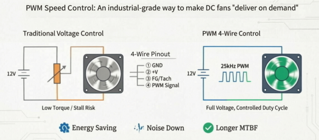
Early DC fans relied on voltage reduction for speed control: 12V dropped to 9V, then 7V, and RPM followed accordingly. This approach was simple in circuitry, but the side effects were significant—motor torque drops with the square of voltage, leading to weak startup in cold conditions, stall risk under backpressure, poor linearity, and essentially uncontrollable behavior in the low-speed range.
The mainstream answer in modern industrial and server cooling is PWM (Pulse Width Modulation) . Instead of varying voltage, PWM keeps the fan powered at its full rated voltage (12V or 24V) at all times. A dedicated signal line carries a high-frequency square wave from the controller, and the duty cycle (percentage of high time) tells the fan exactly how fast to spin.
1. The Essence of PWM Control: Replacing “Voltage Magnitude” with “Time Proportion”
A PWM signal is a fixed-frequency square wave. For DC fans, the industry standard is approximately 25 kHz—above the human hearing threshold of 20 kHz, avoiding audible whine.
- 100% duty cycle → Equivalent to full speed
- 50% duty cycle → Half on, half off → Approximately half speed
- 20%–30% duty cycle → Low-speed standby (exact value depends on minimum startup duty cycle per model)
- 0% duty cycle → Shutdown or hold at minimum RPM (varies by manufacturer design)
The fan’s internal driver IC translates the PWM signal into commutation timing. Because the motor windings always receive the full bus voltage, torque does not collapse at low speeds, and startup remains reliable—this is the core reason PWM outperforms voltage-based speed control.
2. 4-Wire PWM Fan Pinout and Roles
The standard 4-wire interface (derived from Intel’s PWM Fan Specification) assigns each pin as follows:
| Pin | Signal | Description |
|---|---|---|
| 1 | GND | Ground reference |
| 2 | +V (12V / 24V) | Constant power supply—not involved in speed regulation |
| 3 | FG / Tach | Speed feedback (open-drain output, requires pull-up resistor)—returns actual RPM |
| 4 | PWM | Control input—receives 25 kHz square wave from MCU, PLC, BMC, or temperature control board |
With both FG (frequency generator/tachometer) and PWM, the system can implement closed-loop temperature control: temperature sensor → calculate target RPM → adjust duty cycle → verify via FG readback, forming PID or lookup-table-based control.
3. Why Industrial Equipment Should Choose PWM Fans
- Energy saving: At light load, running at 30% duty cycle consumes far less power than constant full-speed operation.
- Quiet operation: Eliminates the “always at full blast” wind noise—nighttime server rooms and medical equipment experience a dramatic difference.
- Extended lifespan: Bearing wear correlates strongly with RPM. Sustained medium/low-speed operation can significantly increase MTBF.
- Precision: The duty-cycle-to-RPM curve can be specified in the datasheet, with batch consistency far superior to voltage-regulation schemes.
- System integration: Directly controllable by BMS, PLC, server BMC, supporting multi-fan synchronization.
4. Common Pitfalls in Selection and Testing
- Frequency must be correct: The controller output must be within 20–28 kHz (most specify 25 kHz). Using 1 kHz will produce audible humming or even vibration.
- Minimum startup duty cycle: Many fans cannot start below 10%–15%. Do not set your temperature control curve too low, or choose a model with soft-start capability.
- PWM pin floating behavior: Some fans default to full speed when the PWM pin is floating (fail-safe), while others stop entirely. Always consult the datasheet before connecting.
- Signal level: 5V TTL is most common. For 3.3V MCUs, consider adding a level shifter or verifying fan compatibility.
- Cable length and EMI: PWM is a digital signal line. Long traces require consideration of voltage drop and interference. In industrial environments, shielded cable or a drive buffer is recommended.
5. One-Sentence Positioning
PWM is not simply about “making a fan run slower.” It upgrades the fan from a device that “spins wildly once powered” to an actuator that understands system commands. For equipment with fluctuating thermal loads that also demands quiet operation and long service life—servers, energy storage cabinets, telecom power supplies, medical electronics, industrial control enclosures—the 4-wire PWM fan is essentially the default answer.